
CNC milling: a practical guide from a manufacturer with 50 years of experience
What is CNC milling and how does it differ from turning?
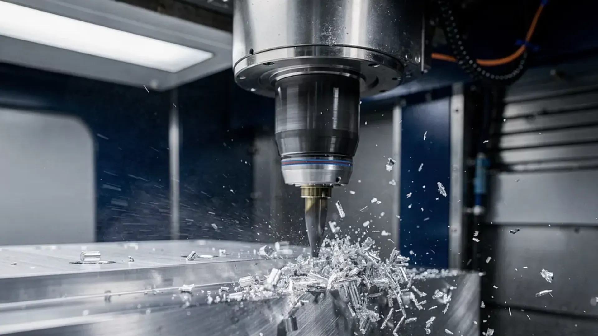
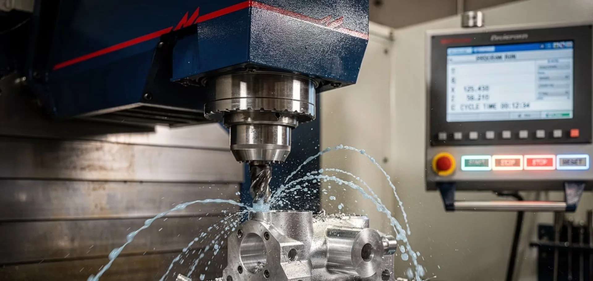
CNC milling is a machining process in which a rotating multi-edge tool (the milling cutter) removes material from a stationary workpiece to achieve the desired shape. Computer numerical control (CNC) directs the machine's movements with micrometric precision, following toolpaths programmed from the CAD/CAM design.
Unlike CNC turning, where the workpiece rotates about an axis and the tool remains stationary, in CNC milling the workpiece is fixed and it is the tool that travels along multiple axes. This makes it possible to machine complex geometries, irregular surfaces and asymmetric parts that turning cannot resolve.
| Aspect | CNC milling | CNC turning |
|---|---|---|
| Workpiece movement | Stationary | Rotates about its axis |
| Tool | Rotating, multi-edge | Stationary, single-point |
| Typical axes | 3 to 5 | 2 (X, Z) |
| Ideal geometry | Prismatic, complex surfaces | Cylindrical, axisymmetric |
| Typical parts | Housings, frames, moulds, tooling | Shafts, bushings, fittings |
At MECVIL we carry out both processes in our CNC machining facilities, with capacity for parts ranging from a few centimetres to 20 metres in length.
Types of CNC milling in industrial manufacturing
CNC milling encompasses a range of operations depending on the geometry of the part, the type of cutter and the direction of cut. In our Sallent workshop we work with these variants on a daily basis:
- Face milling (surfacing): the most common operation. The cutter works with its face to create flat surfaces. It is the starting point for preparing the reference faces of any workpiece.
- Peripheral (slab) milling: the cutter works with its periphery to machine horizontal or lateral surfaces. Used on beds, frames and long structural components.
- Cavity and pocket milling: material removal to create recesses, pockets and internal geometries. Requires well-planned roughing and finishing strategies to avoid vibration.
- Slotting: creation of slots, keyways and precision guides. Critical for shafts, beds and transmission elements.
- Contour and 3D profile milling: for curved surfaces, moulds and parts with organic geometry. Demands advanced CAM programming and, in many cases, 5-axis machining.
- Thread milling (interpolation): creation of internal and external threads via helical toolpaths. More flexible than tapping, especially in hard materials.
The choice of milling type depends on the final geometry, the material, the required tolerance and the production volume. In practice, a complex part combines several of these operations in a single set-up.
Do you have a CNC milling project?
Request a quotation and our technical team will evaluate your drawings, materials and tolerances.
3-axis vs 5-axis milling: when to use each
The difference between 3-axis milling and 5-axis milling is one of the most significant technical decisions in CNC machining. Three-axis machining covers approximately 80 % of industrial applications, but when a part presents complex geometries, the step up to 5 axes makes the difference.
| Aspect | 3-axis | 5-axis |
|---|---|---|
| Movements | X, Y, Z (linear) | X, Y, Z + 2 rotational |
| Geometry | Flat, prismatic surfaces | Compound curves, undercuts, organic forms |
| Set-ups required | Multiple (reposition the part) | A single one (access from any angle) |
| Precision | Good, limited by repositioning | Superior, no accumulated error |
| Investment | Lower | Higher, more complex CAM programming |
| Typical applications | ~80 % of industrial parts | Aerospace, moulds, turbine blades |
When does 5-axis make sense? When the part has angled surfaces, undercuts or deep cavities that would require multiple repositionings on a 3-axis machine. Each repositioning introduces a positioning error and consumes machine time. Five-axis machining eliminates both problems.
At MECVIL we have simultaneous 5-axis machining centres and fixed-bed milling machines with travels of up to 20 metres, enabling us to tackle both complex parts and large-dimension parts with the same precision.
Materials: aluminium, steel, stainless and more
Each material behaves differently under the cutter. Cutting parameters (speed, feed rate, depth of cut) must be adapted to obtain the best finish without compromising the tool or the workpiece.
- Aluminium (6061-T6, 7075): excellent machinability, allows high cutting speeds and a good surface finish. It is the go-to material for structural profile machining in the rail, aerospace and defence sectors.
- Carbon steel (1018, 1045): good machinability, economical and widely available. Ideal for tooling, beds and structural components.
- Stainless steel (304, 316): corrosion-resistant but work-hardens during machining. Requires lower speeds, rigid clamping and abundant coolant.
- Titanium (Ti-6Al-4V, Grade 5): exceptional strength-to-weight ratio, but very difficult to machine. Demands specialised tooling, reduced speeds and careful chip-evacuation strategies.
- Cast iron (grey, ductile): rigid and vibration-absorbent. Chips are abrasive, so tool wear is greater.
- Engineering plastics (POM, PEEK, nylon, PTFE): low cutting forces, but require sharp tools to prevent the material from melting due to heat.
At MECVIL we machine these materials daily on projects ranging from die-cast aluminium tooling to steel structures with certified welding and quality control under our ISO 9001 system.
Tolerances and surface finish in CNC milling
The ability to achieve tight tolerances is what sets industrial CNC milling apart from conventional machining. Standard tolerances follow the ISO 2768 standard, which defines four precision classes:
| Dimensional range | Fine (f) | Medium (m) | Coarse (c) |
|---|---|---|---|
| 0.5 – 6 mm | ±0.05 mm | ±0.1 mm | ±0.3 mm |
| 6 – 30 mm | ±0.1 mm | ±0.2 mm | ±0.5 mm |
| 30 – 120 mm | ±0.15 mm | ±0.3 mm | ±0.8 mm |
| 120 – 400 mm | ±0.2 mm | ±0.5 mm | ±1.2 mm |
| 400 – 1,000 mm | ±0.3 mm | ±0.8 mm | ±2.0 mm |
The most common reference on industrial drawings is ISO 2768-mK (medium linear tolerance + geometric tolerance K). For precision applications, ±0.025 mm is achievable, and in specialised cases (medical, optical) down to ±0.005 mm.
Surface finish is measured in Ra (arithmetic mean roughness):
- Ra 3.2 µm: standard CNC machining finish, no additional operation
- Ra 1.6 µm: finishing pass with optimised parameters
- Ra 0.8 µm: requires grinding or high-speed milling with a dedicated tool
- Ra 0.4 µm: requires grinding or lapping as a secondary operation
At MECVIL we verify every part with coordinate measuring systems and document the results as part of our ISO 9001 quality system.
How to choose an industrial CNC milling supplier
Not all CNC milling workshops offer the same guarantees. When selecting a manufacturing partner, evaluate the following criteria:
- 1.Dimensional capacity: can they machine the part size you need? A workshop with limited travels will not be able to handle large-format parts.
- 2.Number of axes: do they have simultaneous 5-axis capability? This determines whether they can produce complex geometries in a single set-up.
- 3.Machine park: a range of machines (milling machines, lathes, grinders) makes it possible to complete the entire project without subcontracting intermediate stages.
- 4.Certifications: ISO 9001 for quality management and welding processes, together with credentials such as CEPYME500 and EcoVadis. Ask for a current copy of the certificates.
- 5.Sector experience: a workshop that serves 13 industrial sectors has the perspective and protocols to adapt to each one's regulatory requirements.
- 6.Dimensional inspection: ask about their measuring systems and the traceability of inspections.
At MECVIL we combine 3-axis and 5-axis CNC milling machines, fixed-bed milling machines with travels of up to 20 metres, CNC lathes, grinders and 3D measuring systems across more than 10,500 m² of facilities. This allows us to manage turnkey projects — from engineering to assembly — without relying on third parties.
Large-dimension CNC milling: parts up to 20 metres
Milling large parts is one of the specialities that set us apart. Since 1996, when we acquired the first long-travel fixed-bed milling machine in Catalonia, we have machined components up to 20 metres long for sectors such as rail, energy and heavy manufacturing.
This type of CNC milling presents specific challenges:
- Thermal distortion: on long parts, expansion caused by ambient temperature and cutting heat affects the final geometry. Thermal compensation and in-process measurement are required.
- Clamping and fixturing: multi-tonne parts need purpose-built tooling and overhead cranes to position them on the machine table.
- Roughing strategy: on parts with large volumes of material to remove, the sequence of passes must be planned to minimise residual stresses.
- Logistics: transporting parts between 5 and 20 metres long requires dedicated logistical planning.
For more detail on this speciality, see our dedicated article on large-dimension CNC machining.
Need to mill large-format or geometrically complex parts?
At MECVIL we combine fixed-bed milling machines (up to 20 m), 5-axis centres and more than 50 years of experience. Contact our technical team to evaluate your project.